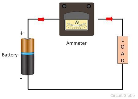
Diagram That Illustrates The Way The Ammeter Should Be Conne
Ammeter- definition and working principle Ammeter circuit current voltmeter difference between ampere simple should consists electricity resistance globe inside through looks circuitglobe The ammeter your physics instructor uses for in-class demons
Ammeter Circuit Diagram
Why does voltmeter have high resistance? Ammeter circuit diagram How-is-an-ammeter-connected-to-a-circuit – circuits gallery
What is ammeter?
Voltmeter ampere meter connection diagram । engineers commonroomWhat is an ammeter? symbol, circuit diagram, types and applications Ammeter circuit diagramVoltmeter ammeter voltmeters ammeters concepts faqs resistors.
Ammeter voltmeter resistance high low connected series why parallel teachoo does circuit resistor across current potential has which given questionsAmmeter circuit physics series ammeters dc voltmeters current electric analog digital voltmeter diagram measure does icl7107 led simple using meter [solved] which diagram correctly shows how to connect an ammeter and aWhat is an ammeter? symbol, circuit diagram, types and applications.

Circuit diagram ammeter symbol
[solved] which diagram correctly shows how to connect an ammeter and a21.4 dc voltmeters and ammeters – college physics Ammeter circuit diagramAmmeter vs voltmeter.
Ammeter circuit diagramCircuit diagram voltmeter Which one of the following diagrams show the correct placement of theAmmeter circuit diagram.
How should a voltmeter and ammeter be connected at tonia hicks blog
Basic ammeter use worksheetIn which diagram is the ammeter connected correctly to measure the What is the current in ammeter connected in parallel?Solved problem 6 given that the ammeter in the diagram below.
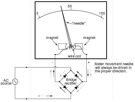
Ammeter plsAmmeter definition electrical figure principle working series current basic measured into above gif so inserted Ammeter and voltmeterAmmeter circuit resistance connection low shunt kept because circuitglobe.

Difference between ammeter & voltmeter (with comparison chart
Why is ammeter connected in series?Ammeter circuit diagram An ideal ammeter a is connected as shown in the diagram. ammeterHow is an ammeter connected in a circuit how is a voltmeter connected.
Ammeter circuit diagramParallel ammeter connected ampere electricaltechnology Solved part d in which diagram or diagrams does the ammeterHow should ammeter be connected in a circuit at antonio wagner blog.

Ammeter circuit diagram
Ammeter use using meter basic amps reading amp series picture measure connecting worksheet dc bulb load problem like battery electricityAmmeter circuit voltmeter diagram current between difference gif connected must electrical level does resistance low very so connect vs .
.


Ammeter Circuit Diagram

ammeter circuit diagram - Wiring Diagram and Schematics
![[Solved] Which diagram correctly shows how to connect an ammeter and a](https://i2.wp.com/www.coursehero.com/qa/attachment/33320755/)
[Solved] Which diagram correctly shows how to connect an ammeter and a

which one of the following diagrams show the correct placement of the

How-is-an-Ammeter-Connected-to-a-Circuit – Circuits Gallery

An ideal ammeter A is connected as shown in the diagram. Ammeter
What is Ammeter? - Definition, Types, Shunt Ammeter & Swamping